
7-Way trailer wiring diagram with brakes is essential for anyone who tows a trailer, ensuring safe and reliable operation of your trailer’s lights, brakes, and other functions. This guide provides a comprehensive overview of the 7-way wiring system, from understanding its components to troubleshooting common issues and installing the wiring correctly.
Whether you’re a seasoned trailer owner or a first-time tow enthusiast, understanding the 7-way wiring diagram is crucial for a safe and enjoyable towing experience. This guide will walk you through the basics of the system, including the purpose of each wire, the different circuits involved, and how to diagnose and fix potential problems.
We’ll also provide step-by-step instructions for installing a 7-way wiring system, ensuring you can confidently connect your trailer to your tow vehicle.
Understanding 7-Way Trailer Wiring
A 7-way trailer wiring system is a standard connector found on most modern trailers. It provides a reliable and efficient way to connect a trailer to a towing vehicle, allowing for the transfer of power and signals.
Purpose of Each Wire, 7-way trailer wiring diagram with brakes
Each wire in a 7-way trailer wiring system serves a specific purpose. The arrangement of wires and their corresponding functions is standardized to ensure compatibility between towing vehicles and trailers.
Understanding a 7-way trailer wiring diagram with brakes can be a bit like learning a new language. You need to decipher the symbols and connections, just as you need to understand the different ways to communicate verbs, like using tenses and moods.
Once you grasp the basics, you’ll be able to confidently hook up your trailer and enjoy the open road.
- Ground (White):This wire provides a common ground connection for all electrical components on the trailer. It is essential for the proper functioning of all circuits.
- Left Turn Signal (Yellow):This wire carries the signal for the left turn signal lights on the trailer. It is connected to the left turn signal circuit in the towing vehicle.
- Right Turn Signal (Green):This wire carries the signal for the right turn signal lights on the trailer. It is connected to the right turn signal circuit in the towing vehicle.
- Tail Lights (Brown):This wire carries the power for the tail lights on the trailer. It is connected to the tail light circuit in the towing vehicle.
- Electric Brakes (Blue):This wire carries the signal to activate the electric brakes on the trailer. It is connected to the brake controller in the towing vehicle.
- Running Lights (Red):This wire carries the power for the running lights on the trailer. It is connected to the running light circuit in the towing vehicle.
- Battery Power (Black):This wire provides power to the trailer’s electrical system, such as interior lights, pumps, and other accessories. It is connected to the battery in the towing vehicle.
Functions of Different Circuits
The 7-way trailer wiring system comprises multiple circuits that work together to ensure safe and efficient operation.
Understanding a 7-way trailer wiring diagram with brakes is crucial for ensuring safe towing. A well-connected system ensures proper functionality of your trailer’s lights and brakes. This knowledge can be applied to other areas, like the way of wade all city 11 v2 , which features a robust wiring system for its various components.
Having a firm grasp on wiring diagrams will help you troubleshoot any issues and maintain your trailer in top condition.
- Brake Lights:The brake light circuit is activated when the driver of the towing vehicle presses the brake pedal. This sends a signal to the trailer’s brake lights, warning drivers behind the vehicle that the towing vehicle is slowing down.
- Turn Signals:The turn signal circuit is activated when the driver activates the turn signal in the towing vehicle. This sends a signal to the trailer’s turn signal lights, indicating the direction of the turn.
- Running Lights:The running light circuit provides power to the trailer’s tail lights, license plate lights, and side marker lights. These lights are always on when the towing vehicle’s headlights are on, ensuring visibility and safety.
- Ground:The ground circuit provides a return path for the electrical current flowing through the other circuits. This ensures that the electrical current can flow smoothly and safely.
Importance of Proper Wiring
Proper wiring is crucial for the safe and reliable operation of a trailer. Incorrect wiring can lead to a variety of issues, including:
- Malfunctioning lights:Improper wiring can cause lights to malfunction, such as failing to turn on or staying on constantly.
- Electrical shorts:Incorrect wiring can create electrical shorts, which can damage electrical components and potentially cause a fire.
- Faulty brakes:Improper wiring can lead to faulty brakes, which can result in an accident.
Typical 7-Way Trailer Wiring Diagram with Brakes


This section provides a visual representation of a standard 7-way trailer wiring diagram, along with a detailed table outlining the wire color, function, and corresponding pin number on the 7-way connector. It also explains the connection points for each wire on the tow vehicle and trailer.
Understanding a 7-way trailer wiring diagram with brakes is essential for ensuring safe and reliable towing. While this diagram focuses on electrical connections for trailer lights and brakes, a similar principle applies to the plumbing of a hot tub, where components like a hottub one-way valve regulate water flow.
Just as the trailer wiring diagram helps you troubleshoot electrical issues, a thorough understanding of hot tub plumbing can help you diagnose and resolve any water flow problems.
7-Way Trailer Wiring Diagram
The 7-way trailer wiring diagram is a standard for connecting trailers to tow vehicles. It consists of seven pins, each assigned a specific function. The diagram below illustrates the typical arrangement of these pins and their corresponding functions.[Image Description: A 7-way trailer wiring diagram is shown, with a rectangular connector labeled “7-Way Trailer Connector” at the top.
Each of the seven pins is numbered from 1 to 7, with a wire attached to each pin. The wires are labeled with their corresponding functions: 1. Ground, 2. Left Turn Signal, 3. Right Turn Signal, 4.
Understanding a 7-way trailer wiring diagram with brakes is crucial for ensuring safe towing, and it’s just as important to consider the aesthetic and practical aspects of your driveway. For a unique and durable option, consider pebble driveways , which offer both visual appeal and resilience.
Once you’ve got your driveway sorted, you can confidently focus on ensuring your trailer’s electrical system is properly wired and ready for the road.
Tail Lights, 5. Running Lights, 6. Brake Lights, and 7. Electric Brake Control. Arrows point to the direction of the electrical flow for each wire.]
7-Way Trailer Wiring Diagram Table
The following table provides a detailed breakdown of the wire colors, functions, and pin numbers for a standard 7-way trailer wiring diagram:| Wire Color | Function | Pin Number ||—|—|—|| White | Ground | 1 || Yellow | Left Turn Signal | 2 || Green | Right Turn Signal | 3 || Brown | Tail Lights | 4 || Blue | Running Lights | 5 || Red | Brake Lights | 6 || Black | Electric Brake Control | 7 |
Understanding a 7-way trailer wiring diagram with brakes is essential for safe towing, especially when it comes to activating the trailer’s brake lights. While you’re figuring out those electrical connections, you might find yourself wishing for a cheat code like the ones in the video game “Rick and Morty: A Way Back Home,” rick and morrty a way back home cheats , but unfortunately, there’s no shortcut to understanding your trailer’s wiring system.
A good wiring diagram will help you troubleshoot any issues and ensure that your trailer is properly equipped for safe towing.
Connection Points
The 7-way connector on the tow vehicle is typically located in the rear bumper area, while the 7-way connector on the trailer is usually located on the tongue. The wires from the tow vehicle are connected to the corresponding pins on the trailer connector.
For example, the white wire (ground) from the tow vehicle is connected to pin 1 on the trailer connector, the yellow wire (left turn signal) is connected to pin 2, and so on.
Troubleshooting Common Wiring Issues


Even with careful installation, 7-way trailer wiring can experience problems. Understanding common issues and troubleshooting steps can save time and frustration. This section explores typical problems and provides practical solutions.
Identifying Common Wiring Issues
Several issues can arise with 7-way trailer wiring, causing malfunctions or complete failure. Identifying these issues is the first step towards resolving them.
- Blown Fuses:Overloaded circuits or short circuits can cause fuses to blow, interrupting power to the trailer’s lights and brakes. This is a common issue, especially when using high-wattage trailer lights or encountering faulty wiring.
- Loose Connections:Loose connections at the 7-way connector, wiring harness, or trailer lights can lead to intermittent or complete loss of power. Vibration during towing can cause connections to loosen over time.
- Faulty Wiring:Damaged or corroded wiring can disrupt the electrical flow, leading to malfunctioning lights or brakes. This can occur due to wear and tear, exposure to harsh conditions, or improper installation.
- Incorrect Wiring:Incorrect wiring connections can result in unintended functions or even damage to the trailer’s electrical system. This is often due to mismatched wiring diagrams or accidental misconnections.
Troubleshooting Steps
Systematic troubleshooting can help pinpoint the source of a wiring problem. The following steps provide a structured approach:
- Inspect the Fuses:Begin by visually inspecting the fuses in the tow vehicle and trailer. Look for blown fuses, which will have a broken filament or melted wire.
- Check for Loose Connections:Examine all connections at the 7-way connector, wiring harness, and trailer lights. Ensure they are securely fastened and free from corrosion.
- Test Continuity and Voltage:Use a multimeter to test the continuity and voltage of each wire. Continuity checks ensure a complete electrical path, while voltage checks confirm power flow.
- Trace Wiring:If continuity or voltage issues are found, trace the wiring back from the affected component to identify any breaks, damage, or corrosion.
- Verify Wiring Diagram:Compare the wiring connections to the correct wiring diagram for your trailer and tow vehicle. Ensure all wires are connected to the appropriate terminals.
Using a Multimeter
A multimeter is an essential tool for diagnosing electrical issues. It can measure continuity, voltage, and current, providing valuable insights into the wiring’s health. Here’s how to use a multimeter effectively:
- Continuity Test:To test continuity, set the multimeter to the “ohms” setting. Place the probes on the ends of the wire being tested. A reading close to zero indicates continuity, while a high reading or “OL” (open loop) signifies a break in the circuit.
Understanding a 7-way trailer wiring diagram with brakes is crucial for ensuring safe towing. It’s important to correctly connect the brake lights, turn signals, and running lights to the trailer. While you’re focused on those connections, you might be tempted to take a break and enjoy some milky way fun xize – but don’t forget to double-check those wiring diagrams before hitting the road!
- Voltage Test:To test voltage, set the multimeter to the “DC voltage” setting. Place the red probe on the positive terminal of the circuit and the black probe on the negative terminal. A reading within the expected range indicates proper voltage flow.
For example, a tail light circuit should typically have 12 volts.
Note:Always exercise caution when working with electrical systems. Disconnect the battery before working on any wiring to prevent shocks or injury.
Wiring Installation and Modification: 7-way Trailer Wiring Diagram With Brakes
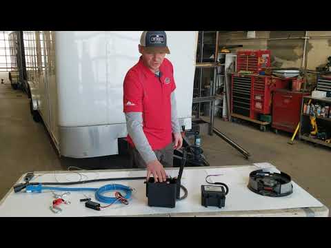
Installing a 7-way trailer wiring system involves connecting the trailer’s wiring to the tow vehicle’s electrical system. This connection allows the tow vehicle to control the trailer’s lights, brakes, and other electrical functions.
Installing a 7-Way Trailer Wiring System
Installing a 7-way trailer wiring system involves connecting the trailer’s wiring to the tow vehicle’s electrical system. This connection allows the tow vehicle to control the trailer’s lights, brakes, and other electrical functions.
Understanding a 7-way trailer wiring diagram with brakes is essential for safe towing, especially when dealing with larger trailers. While this diagram focuses on electrical connections, it’s interesting to note how technology influences various industries. For instance, the use of two way mirror acrylic tap plastic in architectural design has gained popularity for its unique optical properties.
Returning to trailer wiring, ensuring proper connections and functionality is crucial for safe and reliable towing.
- Gather the necessary materials: You will need a 7-way trailer wiring harness, a 7-way trailer connector, wire strippers, electrical tape, and a crimping tool.
- Locate the tow vehicle’s wiring: The tow vehicle’s wiring is typically located in the rear bumper area. The wiring may be exposed or covered with a protective sheath.
- Connect the 7-way trailer wiring harness to the tow vehicle’s wiring: This involves connecting the individual wires of the harness to the corresponding wires of the tow vehicle’s electrical system. Use a wiring diagram to ensure proper connections. The wiring harness typically comes with color-coded wires to make installation easier.
- Connect the 7-way trailer connector to the 7-way trailer wiring harness: This connector will be mounted on the tow vehicle’s rear bumper. Securely attach the connector to the harness using the appropriate fasteners.
- Test the wiring: Once the wiring is installed, test the connections by connecting the trailer to the tow vehicle and turning on the trailer’s lights and brakes. Ensure that all lights and functions are working properly.
Connecting the Wiring to the Tow Vehicle’s Electrical System
Connecting the 7-way trailer wiring system to the tow vehicle’s electrical system involves identifying the correct wires and making secure connections. This process typically involves splicing into the tow vehicle’s existing wiring or connecting to a dedicated trailer wiring harness.
- Identify the tow vehicle’s wiring: The tow vehicle’s wiring is typically located in the rear bumper area. The wiring may be exposed or covered with a protective sheath. The wiring diagram for your tow vehicle will indicate the location of the wires for the trailer lights, brakes, and other electrical functions.
- Connect the 7-way trailer wiring harness to the tow vehicle’s wiring: This involves connecting the individual wires of the harness to the corresponding wires of the tow vehicle’s electrical system. Use a wiring diagram to ensure proper connections. The wiring harness typically comes with color-coded wires to make installation easier.
In some cases, the wiring harness may be designed to plug directly into the tow vehicle’s electrical system, eliminating the need for splicing.
- Secure the connections: Use electrical tape or wire connectors to ensure that the connections are secure and waterproof. It is important to ensure that all connections are properly insulated to prevent shorts or other electrical problems.
Modifying Existing Wiring Systems
Modifying an existing wiring system to accommodate a 7-way trailer connector involves identifying the existing wiring and adding the necessary wires for the 7-way connector.
- Identify the existing wiring: Determine the existing wiring for the trailer lights and brakes. Use a wiring diagram for your tow vehicle to help identify the correct wires.
- Add the necessary wires: Splice the new wires from the 7-way trailer wiring harness into the existing wiring for the trailer lights, brakes, and other electrical functions. Ensure that the wires are properly connected and insulated to prevent shorts or other electrical problems.
- Secure the connections: Use electrical tape or wire connectors to ensure that the connections are secure and waterproof. It is important to ensure that all connections are properly insulated to prevent shorts or other electrical problems.
Final Thoughts
By understanding the intricacies of the 7-way trailer wiring system, you can ensure your trailer’s lights, brakes, and other functions operate flawlessly. This guide has provided a comprehensive overview of the system, from its components and circuits to troubleshooting common issues and installing the wiring correctly.
Remember, proper wiring is crucial for a safe and enjoyable towing experience. With this knowledge, you’re equipped to confidently connect your trailer and enjoy the freedom of the open road.
Common Queries
What are the different types of trailer connectors?
There are various types of trailer connectors, including 4-way, 5-way, 6-way, and 7-way. The 7-way connector is the most common for trailers equipped with electric brakes.
What are the most common 7-way wiring problems?
Common problems include blown fuses, loose connections, corroded terminals, and faulty wiring. A multimeter can help diagnose these issues.
Can I install a 7-way wiring system myself?
Yes, you can install a 7-way wiring system yourself with the right tools and knowledge. Many resources are available online and in automotive stores to guide you through the process.
What are the safety precautions when working with electrical wiring?
Always disconnect the battery before working on any electrical wiring. Use insulated tools and wear appropriate safety gear.


