
7 Way Trailer Wiring Diagram is your essential guide to understanding the intricate world of trailer wiring. This diagram is the roadmap for connecting your vehicle to your trailer, ensuring a safe and functional towing experience. Whether you’re a seasoned trailer owner or a curious newcomer, this guide will equip you with the knowledge you need to confidently navigate the world of trailer wiring.
From deciphering the purpose of each wire to understanding the different connector types and color coding, this comprehensive guide will unravel the complexities of 7-way trailer wiring. It will delve into common wiring diagrams, explore troubleshooting techniques, and provide step-by-step instructions for installation and modification.
Understanding 7-Way Trailer Wiring: 7 Way Trailer Wiring Diagram


The 7-way trailer wiring system is a standard electrical connection used to power and control various functions on a trailer. This system is essential for safely and efficiently towing a trailer, ensuring proper lighting, braking, and other critical operations.
Purpose of Each Wire
The 7-way trailer wiring system utilizes seven individual wires, each serving a specific purpose:
- Ground (White):Provides a common ground connection for all electrical components on the trailer.
- Left Turn Signal (Yellow):Controls the left turn signal lights on the trailer.
- Right Turn Signal (Green):Controls the right turn signal lights on the trailer.
- Tail Lights (Brown):Powers the tail lights, brake lights, and running lights on the trailer.
- Electric Brake (Blue):Provides power to the electric brakes on the trailer, if equipped.
- Battery Power (Red):Supplies battery power to the trailer for accessories or other electrical components.
- Reverse Lights (White/Black):Powers the reverse lights on the trailer.
Types of Connectors
The 7-way trailer wiring system utilizes two primary types of connectors:
- 7-Way Flat Connector:This is the most common type of connector, featuring seven flat terminals arranged in a rectangular configuration. It is commonly found on vehicles and trailers.
- 7-Way Round Connector:This connector type features seven round terminals arranged in a circular configuration. It is less common than the flat connector but is still used in some applications.
Color Coding, 7 way trailer wiring diagram
The 7-way trailer wiring system employs a standardized color coding system to ensure proper wiring connections:
| Wire Function | Color Code |
|---|---|
| Ground | White |
| Left Turn Signal | Yellow |
| Right Turn Signal | Green |
| Tail Lights | Brown |
| Electric Brake | Blue |
| Battery Power | Red |
| Reverse Lights | White/Black |
Common Trailer Wiring Diagrams


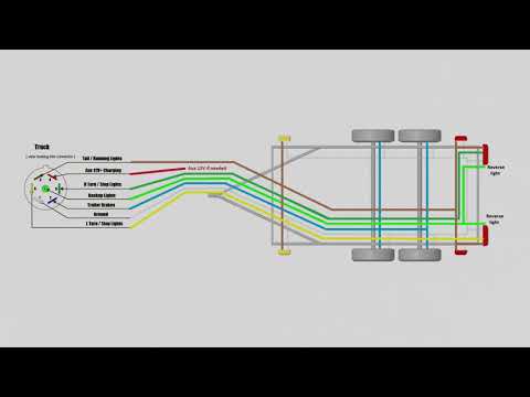
A 7-way trailer wiring diagram is a visual representation of the electrical connections between a towing vehicle and a trailer. These diagrams are crucial for understanding the functionality of each wire and ensuring proper installation. They help to troubleshoot any wiring issues and guarantee safe and reliable operation of the trailer’s lights, brakes, and other electrical components.
Standard 7-Way Trailer Wiring Diagram
The standard 7-way trailer wiring diagram is the most common configuration used for trailers in North America. It consists of seven pins, each assigned a specific function.
Understanding a 7-way trailer wiring diagram can be a bit like piecing together a puzzle, but it’s essential for safely connecting your trailer to your vehicle. Just as important is fostering a love of history in our children, and there are many engaging ways to do so.
Learn more about how to encourage children over US history Once you’ve mastered the 7-way wiring diagram, you’ll be ready to hit the road and create lasting memories with your family, perhaps even visiting historical sites along the way.
- Pin 1: Ground (White): This pin serves as the common ground for all trailer electrical components.
- Pin 2: Left Turn Signal/Tail Light (Green): This pin carries the signal for the left turn signal and tail light.
- Pin 3: Right Turn Signal/Tail Light (Yellow): This pin carries the signal for the right turn signal and tail light.
- Pin 4: Brake Lights (Red): This pin carries the signal for the trailer brake lights.
- Pin 5: Ground (White): This pin serves as an additional ground for the trailer electrical system.
- Pin 6: Battery Power (Brown): This pin provides a direct connection to the towing vehicle’s battery, supplying power to the trailer’s running lights, interior lights, and other accessories.
- Pin 7: Trailer Electric Brakes (Blue): This pin carries the signal for the trailer’s electric brakes, activating the brakes when the towing vehicle applies its brakes.
Troubleshooting 7-Way Trailer Wiring
Troubleshooting 7-way trailer wiring can be a frustrating experience, but with a systematic approach, you can isolate and fix the problem efficiently. Understanding the common issues and their causes is crucial for effective troubleshooting.
Common Issues and Causes
Common issues with 7-way trailer wiring can stem from various factors, including faulty connections, damaged wires, blown fuses, and incorrect wiring configurations.
- Faulty Connections:Loose or corroded connections at the trailer plug, tow vehicle connector, or wiring harness can interrupt the electrical flow, causing malfunctions.
- Damaged Wires:Abrasion, cuts, or pinched wires can result in open circuits, leading to signal loss or complete failure of specific functions.
- Blown Fuses:Overloading a circuit or a short circuit can blow fuses, preventing power from reaching the trailer’s electrical components.
- Incorrect Wiring Configuration:Mismatched wiring between the tow vehicle and trailer can lead to incorrect functionality, potentially causing damage to the electrical system.
Troubleshooting Steps
Troubleshooting 7-way trailer wiring involves a systematic approach to identify and address the underlying issue.
Understanding a 7-way trailer wiring diagram is crucial for safe and reliable towing. It’s like the lifeline connecting your vehicle to the trailer, ensuring lights, brakes, and other functions work seamlessly. Just like the yocom hospital history of building chariton iowa tells the story of a community’s healthcare journey, the 7-way diagram provides a roadmap for safe towing, ensuring everything runs smoothly on the road.
- Visual Inspection:Start by visually inspecting the trailer plug, tow vehicle connector, and wiring harness for any visible damage, loose connections, or corrosion. Ensure all wires are properly secured and free from any signs of wear or tear.
- Check Fuses:Inspect the fuses in both the tow vehicle and trailer for blown fuses. If a fuse is blown, replace it with a fuse of the same amperage rating. Note that a blown fuse might indicate an underlying problem that needs to be addressed.
- Test Continuity:Use a multimeter to test the continuity of each wire in the 7-way connector. Ensure there is a continuous path between the tow vehicle connector and the trailer connector for each wire. If a wire has an open circuit, it needs to be repaired or replaced.
Understanding a 7-way trailer wiring diagram is crucial for anyone towing a trailer, ensuring safe and functional connections. The importance of proper wiring is echoed in the dedication and innovation seen throughout the history of FPVISA , a company that has long championed safe and reliable towing solutions.
From basic lighting to advanced braking systems, the 7-way wiring diagram serves as the foundation for a secure and efficient towing experience.
- Verify Wiring Configuration:Double-check the wiring configuration to ensure that the tow vehicle and trailer connectors are wired according to the standard 7-way trailer wiring diagram. Any mismatched wiring can cause malfunctions and potentially damage the electrical system.
- Check Ground Connection:The ground wire is crucial for proper electrical flow. Ensure the ground connection is clean and tight at both the tow vehicle and trailer connectors. A poor ground connection can lead to erratic behavior or malfunctions.
Troubleshooting Flowchart
| Problem | Possible Cause | Troubleshooting Step |
|---|---|---|
| Tail Lights Not Working | Blown Fuse, Loose Connection, Damaged Wires | Check Fuses, Inspect Connections, Test Wire Continuity |
| Turn Signals Not Working | Blown Fuse, Loose Connection, Damaged Wires, Incorrect Wiring | Check Fuses, Inspect Connections, Test Wire Continuity, Verify Wiring Configuration |
| Brake Lights Not Working | Blown Fuse, Loose Connection, Damaged Wires, Faulty Brake Light Switch | Check Fuses, Inspect Connections, Test Wire Continuity, Check Brake Light Switch |
| Running Lights Not Working | Blown Fuse, Loose Connection, Damaged Wires, Faulty Running Light Switch | Check Fuses, Inspect Connections, Test Wire Continuity, Check Running Light Switch |
| Electric Brakes Not Working | Blown Fuse, Loose Connection, Damaged Wires, Faulty Brake Controller | Check Fuses, Inspect Connections, Test Wire Continuity, Check Brake Controller |
| Trailer Battery Not Charging | Blown Fuse, Loose Connection, Damaged Wires, Faulty Charging System | Check Fuses, Inspect Connections, Test Wire Continuity, Check Charging System |
Installing and Modifying 7-Way Trailer Wiring

Installing a 7-way trailer wiring system can seem daunting, but with the right tools and a little patience, it’s a task that most DIYers can tackle. Whether you’re adding a new trailer hitch or upgrading your existing wiring, this guide will walk you through the process.
Installing a 7-Way Trailer Wiring System
The process of installing a 7-way trailer wiring system typically involves connecting the wiring to your vehicle’s electrical system, mounting the 7-way connector, and running the wiring to the trailer hitch. Here’s a step-by-step guide:
- Locate the Vehicle’s Tail Light Wiring: Identify the taillight wiring harness near your vehicle’s taillights. This harness typically includes wires for the brake lights, turn signals, and running lights. You may need to remove the taillight assembly to access the wiring.
- Connect the 7-Way Wiring Harness: The 7-way wiring harness will have a connector that plugs into the vehicle’s tail light wiring harness. The wiring diagram included with the harness will guide you in connecting the correct wires. Ensure you use the appropriate connectors and terminals.
- Mount the 7-Way Connector: The 7-way connector can be mounted in various locations, such as the rear bumper, trailer hitch, or a dedicated wiring box. Choose a location that is accessible and protected from the elements.
- Run the Wiring: Route the wiring harness from the tail light wiring to the 7-way connector. Use wire loom or cable ties to secure the wiring and prevent chafing. You may need to drill holes or create pathways for the wiring.
- Test the Wiring: After completing the installation, thoroughly test all the functions of the 7-way connector using a test light or a multimeter. Ensure that the brake lights, turn signals, running lights, and other functions are working correctly.
Modifying Existing Wiring for Compatibility
If your vehicle has a 4-way or 5-way trailer wiring system, you may need to modify the wiring to accommodate a 7-way system. This typically involves adding new wires for the additional functions provided by a 7-way connector.
- Identifying Existing Wiring: First, you’ll need to identify the existing wires and their functions. Consult your vehicle’s wiring diagram or use a test light to determine which wires are connected to the brake lights, turn signals, and running lights.
- Adding New Wires: Depending on your existing wiring setup, you may need to add new wires for the battery, ground, electric brakes, and other functions provided by a 7-way connector. You can splice the new wires into the existing harness or run separate wires to the 7-way connector.
- Soldering and Crimping: Use a soldering iron and heat shrink tubing to create secure connections between the new wires and the existing harness. Ensure all connections are properly insulated and protected from the elements.
Verifying a Properly Installed 7-Way Trailer Wiring System
After installing or modifying your 7-way trailer wiring system, it’s essential to verify that it’s working correctly. This involves testing each function of the 7-way connector to ensure it’s properly connected and functioning as intended.
- Visual Inspection: Start by visually inspecting the wiring harness and connections for any damage, loose connections, or exposed wires. Ensure that all connections are securely fastened and properly insulated.
- Test Light or Multimeter: Use a test light or a multimeter to test each function of the 7-way connector. Connect the test light or multimeter to the appropriate terminal on the 7-way connector and then activate the corresponding function on the vehicle, such as the brake lights, turn signals, or running lights.
Understanding a 7-way trailer wiring diagram is crucial for safe towing, ensuring proper functionality of your trailer’s lights and brakes. It’s just as important to know the history of a property before you buy it, like the ownership history of 11985 Heritage Oak Place , to avoid any surprises.
Just as a trailer wiring diagram helps you connect to your trailer, understanding a property’s history helps you connect with its past and make informed decisions.
- Trailer Connection: Finally, connect a trailer to the 7-way connector and test all the functions on the trailer. Ensure that the brake lights, turn signals, running lights, and other functions are working correctly.
Closing Summary
Understanding and mastering 7-way trailer wiring is crucial for any trailer owner. By understanding the basics, you can confidently troubleshoot issues, safely install a wiring system, and enjoy the peace of mind that comes with knowing your trailer is properly connected.
This guide provides a solid foundation for tackling any trailer wiring challenges you may encounter, empowering you to confidently hit the road with your trailer in tow.
FAQ Overview
What are the different types of 7-way trailer connectors?
There are two main types of 7-way trailer connectors: standard and flat. Standard connectors are typically round, while flat connectors are rectangular. Both types have the same functionality and wiring configuration.
Can I use a 7-way trailer wiring diagram for a 4-way connector?
No, a 7-way trailer wiring diagram is specifically designed for 7-way connectors. You’ll need a different wiring diagram for a 4-way connector.
Where can I find a 7-way trailer wiring diagram for my specific vehicle?
You can typically find a wiring diagram in your vehicle’s owner’s manual, or you can search online for a diagram specific to your make and model.


